DropThrowie: Your WiFi Friend
The goal of this portfolio project was to build a device that can be surreptitiously placed to provide targeted and timed deauth of WiFi networks, ephemeral WiFi dead drop capabilities, and zero-log WiFi chat services. This device needed to be able to run for a minimum of 12 hours and have an extremely simple user interface. I wanted to include silicone squishy buttons and build the case so it can be attached to a fishing line for tree and rooftop deployment. I also wanted to ensure the device could be built for less than $10usd. It took 2 months to go from sketch to MVP and I learned a ton along the way.
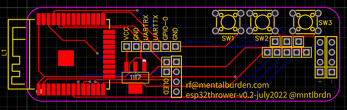
It usually starts with a sketch for the enclosure of the final product, but for this project I needed to build around a PCB. Starting with a block diagram schematic and some dimensional constraints I was able to get a solid starting place.

EasyEDA and JLCPCB/LCSC are my favorite, just make sure to obfuscate your traces and partition the circuit with thru hole headers. This allows you to fly wire the final result while ensuring our friends in shenzen dont “borrow” your idea. Oh, and always run EasyEDA from a VM… Because reasons @_@

About a week later my PCBs were delivered. I got 25 for $20usd with shipping. I got an ESP32-S, ams1117–3.3, a few header pins, and the ssd1306 OLED soldered onto the board. Voltage tests ran clean and no blue smoke appeared, which is always a good sign. I successfully flashed the esp32 with some basic serial test junk code. Then I ran into a problem…

I had no issues when flashing my OLED test code on the breadboard version, it popped up with the logo and text as expected. When I tried to flash the same code onto the PCB version it would immediately go into an SPI FLASH boot error when powered up. Thats because I wasnt paying enough attention to detail in EasyEDA and put the i2c bus on the wrong pins. I was using the pin numbers of the schematic drawing, which dont line up with the GPIO pin assignments. Oh well, stupid mistakes happen… It wasnt a total loss.
I knew I liked the dimensions of the board, the button placement felt alright, the buttons worked as expected with INPUT_PULLUP, and power tests running off a set of 18650’s ran clean for 22 hours. I kept what worked, modified and fixed what didnt, and got to work on v0.2…
20 for $25 this time because I didnt have the coupon. While I waited for the v0.2 boards I got to work on the initial enclosure. Ive started using floral foam (the green crumbly stuff) to mock up enclosure dimensions. Its handy because you can crumple/collapse the foam in your hand until its comfortable to hold, and take measurements from there. Once I had a set of measurements from foam I use clay to get a more solid and weighted object, then its getting that on paper.

About two weeks later I got the v0.2 PCBs and got to work on the next tasks. It felt amazing when the OLED test code flashed successfully and the boot errors went away. I was also pleasantly surprised by how little power the board was using (0.045A±) even when animating the OLED. I tried a power test with a single 18650 and found it ran for 15 hours, which was plenty. The button placement felt much better too.
Now that I had a working screen I threw together an example menu with basic button functionality. I just needed to ensure the buttons worked and I could easily reboot the esp32 when I was running final battery tests.
#include <SPI.h>
#include <Wire.h>
#include <Adafruit_GFX.h>
#include <Adafruit_SSD1306.h>#define SCREEN_WIDTH 128 // OLED display width, in pixels
#define SCREEN_HEIGHT 32 // OLED display height, in pixels
#define SCREEN_ADDRESS 0x3C
Adafruit_SSD1306 display(SCREEN_WIDTH, SCREEN_HEIGHT, &Wire, 4);const byte left = 12;
const byte right = 25;
const byte menu = 33;
byte button_flag = 0;void loop()
{
  if (digitalRead(left) == LOW && button_flag == 0)
  {
    display.clearDisplay();
    display.display();
    button_flag = 1;
    leftbutton();
  }
  if (digitalRead(right) == LOW && button_flag == 0)
  {
    display.clearDisplay();
    display.display();
    button_flag = 1;
    rightbutton();
  }
  if (digitalRead(menu) == LOW && button_flag == 0)
  {
    display.clearDisplay();
    display.display();
    button_flag = 1;
    menubutton();
  }
  if (digitalRead(menu) == LOW && digitalRead(left) == LOW && button_flag == 0)
  {
    display.clearDisplay();
    display.display();
    button_flag = 1;
    restartbutton();
  }
}void restartbutton()
{
  display.setCursor(5,7);
  display.setTextSize(2);
  display.setTextColor(SSD1306_WHITE);
  display.println(F("restarting"));
  display.display();
  delay(3000);
  ESP.restart();
  button_flag = 0;
}void menubutton()
{
  display.setCursor(5,7);
  display.setTextSize(2);
  display.setTextColor(SSD1306_WHITE);
  display.println(F("menu"));
  display.display();
  button_flag = 0;
}void rightbutton()
{
  display.setCursor(5,7);
  display.setTextSize(2);
  display.setTextColor(SSD1306_WHITE);
  display.println(F("right"));
  display.display();
  button_flag = 0;
}void leftbutton()
{
  display.setCursor(5,7);
  display.setTextSize(2);
  display.setTextColor(SSD1306_WHITE);
  display.println(F("left"));
  display.display();
  button_flag = 0;
}void bootmainmenu()
{
  display.clearDisplay();
  display.display();
  display.setCursor(18,7);
  display.setTextSize(1);
  display.setTextColor(SSD1306_WHITE);
  display.println(F("MENTALBURDEN"));
  display.println(F("esp32Thrower v0.2"));
  display.println(F("rf@mentalburden.com"));
  display.display();
}void setup()
{
  Serial.begin(9600);
  display.begin(SSD1306_SWITCHCAPVCC, SCREEN_ADDRESS);
  //display.invertDisplay(true);
  display.display();
  display.clearDisplay();
  display.setTextSize(2);
  display.setTextColor(SSD1306_WHITE);
  display.setCursor(5,7);
  display.println(F("Booting..."));
  display.display();
  delay(1000);
  //run ssid scan here
  for(int16_t xpix = 0; xpix < display.width()-1; xpix++)
  {
    display.drawPixel(xpix, 1, SSD1306_WHITE);
    display.display();
    delay(10);
  }
  delay(500);
  display.clearDisplay();
  display.display();
  pinMode(left, INPUT_PULLUP);
  pinMode(right, INPUT_PULLUP);
  pinMode(menu, INPUT_PULLUP);

  bootmainmenu();
}
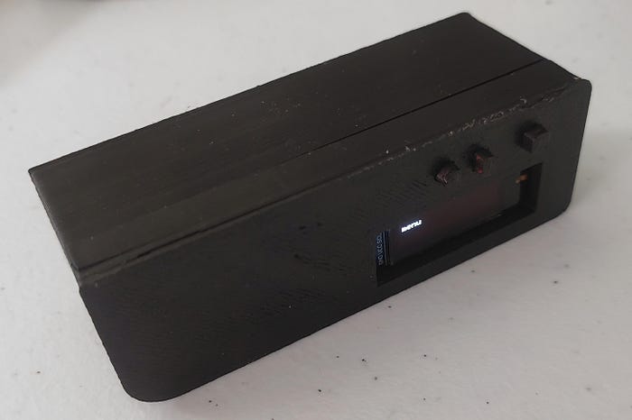
The basics were there and working as expected, time to get the enclosure finished and to cast some buttons in silicone. I printed a one piece button blank which would keep everything aligned properly. Pressing the blank into clay worked great and provided a super easy mold while I was still prototyping.


The board was working great, the case was printed, buttons were cast in silicone, and it felt great to hold the finished MVP. Charging and battery tests ran great.
Time to talk money. To get to this stage of completion I spent $105usd.
Heres the breakdown and BOM:
JLCPCB costs for 45 boards: $46
5x ESP32-S SOCs ($4.3): $21.5
5x AMS1117-3.3 ($.3): $1.5
5x ssd1306 128x32 White OLEDs ($1.9): $9.5
36x header pins: $1
15x 5x5mm SPST Buttons: $1
8g± PLA: $2.5
2hrs SMD soldering: $30 (2x$15 min wage)
7 Hours Design Work: $105 (7x$15 min wage)
Silicone molding and materials: $22 (1x$15 min wage + materials)Project hard costs: $105
Project Total (including 10hrs min wage time): $240
Price per unit: $8.9


Im happy with the final result. Its not ready for field use but its a great prototype that I can pass around a board room. Im glad this project is at a state where I can shelve it for now; V0.3 next year sometime, maybe.
Lessons Learned:
- Pay better attention when designing schematics. I could have saved time and money by not making a super stupid mistake with the i2c lines.
- Dont fall for scope creep. I spent a week thinking about how I could overmold the enclosure in silicone. It would have provided waterproofing, but it was a time sink that could have been spent working towards the MVP.
- Dont use the GPIO pullup/pulldown modes in software. Pullup/pulldown your switches and buttons on the pcb instead.
- Consider using SMD jumpers (0 ohm resistors) instead of flywire jumpers for the circuit partitioning. Its important to ensure the design is segmented, because shenzen, but SMD jumpers are a more elegant solution.
- Start using the IPEX4 connectors on the esp32’s instead of relying on the PCB antenna. This will offer better flexibility with enclosure design and make rf transparency less of an issue.